Build
Introduction
Put your build instructions here! Use lots of photos and detail.
Table of Contents
- Hardware Mods, DXE Active Antenna, BeeLink PC Linux Server Install and WSPRDdaemon Configuration
- Reference and instruction manuals -
- Perform Required RX888 clock-Thermal Kit Installation, DXE-RSEAV1 Antenna Bias-T Disable and LBE-1420 Clock Freq Configuration
- Assemble and Configure the DX Engineering DXE-RSEAV-1 Short Vertical Active Antenna
The standard antenna at the time of writing is the DX Engineering RSEAV-1.
For a roof installation: https://www.dxengineering.com/parts/dxe-rf-pro-1b
flowchart TD
    A[fa:fa-tower-cell GPS Antenna] -->|SMA| Bodnar(Bodnar GPSDO)
    Bodnar -->|Reference Clock Signal| RX888[RX888 SDR]
    Computer -->|5V USB Power| Bodnar
    HF[fa:fa-tower-cell HF Antenna] -->|F/F| CMC[Common Mode Choke]
    CMC -->|F/F| Bias[Bias Tee]
    Bias -->|Input F/F| LPF[Low Pass Filter]
    LPF --> |Out SMA/SMA| RX888
    RX888 --> |Data USB-B/USB-A| Computer
    Computer --> Peripherals[Peripherals fa:fa-computer-mouse fa:fa-desktop fa:fa-keyboard]
    Astron(Astron RS-12A, modified) --> |19V| Computer
Hardware Mods, DXE Active Antenna, BeeLink PC Linux Server Install and WSPRDdaemon Configuration
The actual construction style and design of the RX888 WSPRDaemon SDR PSWS is up to the builder although certain tasks are requied regardless of how the build is performed. The use of the below cabinet, layout and hardware is not required but represents the quality that was put into the K3DFD PSWS build. How you do it is of course, up to you. Regardless, the system must meet the operational performance levels to provide useful data to HamSCI.
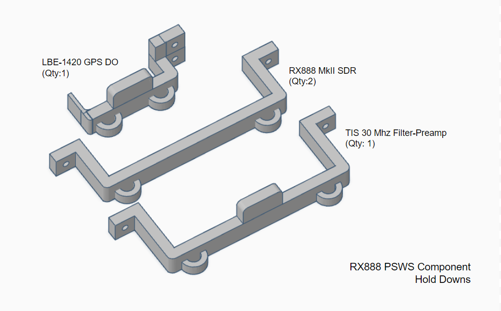
Essentially, the entire PSWS consists of: BeeLink SER Pro 7i 16-32GB 8-core NUC PC with Linux 24.04.x server and WSPRDaemon installed, a RX888 MkII 16-bit ADC Software-defined Radio that provides 30Mhz of spectrum coverage, a Leo Bodnar LBE-1420 GPS-disciplined Oscillator that drives the RX888 clock for GPS sourced timing, a Turn Island Systems (Dual) 30Mhz Filter-preamp to provide antialiasing filtering of signals above 30Mhz, and a low-noise DX Engineering RSEAV1 active vertical antenna.
The components are mounted on an aluminum plate held in place by 3D printed hold downs, M3 hardware, 3M self-adhesive tie-down pads contained in a Zulkit aluminum cabinet. All internal connections consists of high-quality SMA connectors, coax and USB cables. 12VDC is provided to the PSWS components and the active antenna by 1.2 amp linear power supplies. Do not use inexpensive switching supplies. All DC lines are choked to reduce or eliminate any potention RF.
Reference and instruction manuals -
RX888 MkII SDR Source
TAPR Clock kit and thermal Pad
Leo Bodnae LBE-1420 GPS Disciplined Oscillator
TIS 30Mhz Filter-preamp
DX Engineering DXE-RSEAV1 Active Antenna
Component Layout
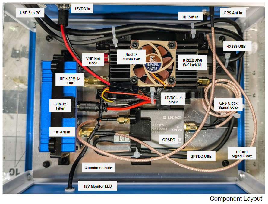
In this instance the system components are mounted on a 6”x8”x1/16” 6061/T651 Aluminum Sheet Metal aluminum plate and contained in a Zultech 9.1”x7.3”x3.9” Project Enclosure using metric M3 hardware
Drill Baseplate Mounting Holes
Use a 4mm drill bit to open holes in the aluminum base plateplate and use M3 screws and nuts to place and affix the 3D hold downs.
3D printed Component Hold Downs
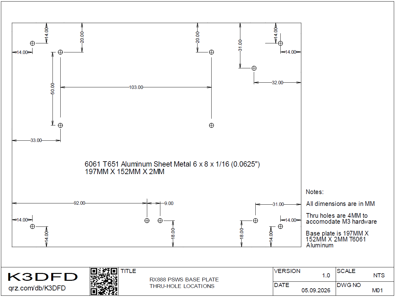
You can use these .stl file to print the component hold down parts that affix the RX888, GPSDO and Filter-Preamp to the aluminum plate. ABS recommended although .20mm layer / 20% infill PLA works well
.stl file for RX888 MkII SDR
.stl file for Leo Bodnar LBE-1420
.stl file for Turn Island Systems 30Mhz Filter-Preamp
Perform Required RX888 clock-Thermal Kit Installation, DXE-RSEAV1 Antenna Bias-T Disable and LBE-1420 Clock Freq Configuration
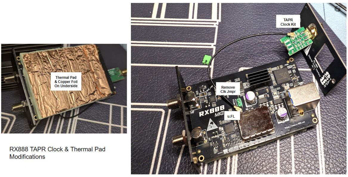
Open up the RX888 MkII SDR and install the TAPR Clock and Thermal Pad kit
Before connecting the RX888 MkII SDR, some hardware modifications are required. The internal oscillator does not meet the 10 mHz accuracy requirement, so the Leo Bodnar LBE-1420 external clock must be connected and configured for 27MHz. Additionally, a thermal pad should be added to the bottom of the board to address heat dissipation. Refer to the RX888 Clock Kit - Thermal Pad Manual for modification instructions and see below:
Remove the endplate from the RX888 MkII SDR on the side with the USB socket. As shown below and in the above instructions, install the Clock and Thermal kit to the SDR. Exercise caution when attaching the coax’s u.FL connector to the center of the board. Remove the plastic jumper to disable the internal clock and activate the Bodnar GPS DO.
Also, attach the rubber pad to the underside of the SDR’s board and the copper tape to the exposed side of the pad. This side will face and press against the body of the SDR to improve heat transfer.
Assemble and Configure the DX Engineering DXE-RSEAV-1 Short Vertical Active Antenna
- The first task is to change the internal J2 and J3 jumper settings to disable the Bias-T power source feature. Move both J2 and J3 jumpers from the 1-2 position to the 2-3 position. Then the required 12VDC will be supplied to the type-F connector on the front of the antenna box.
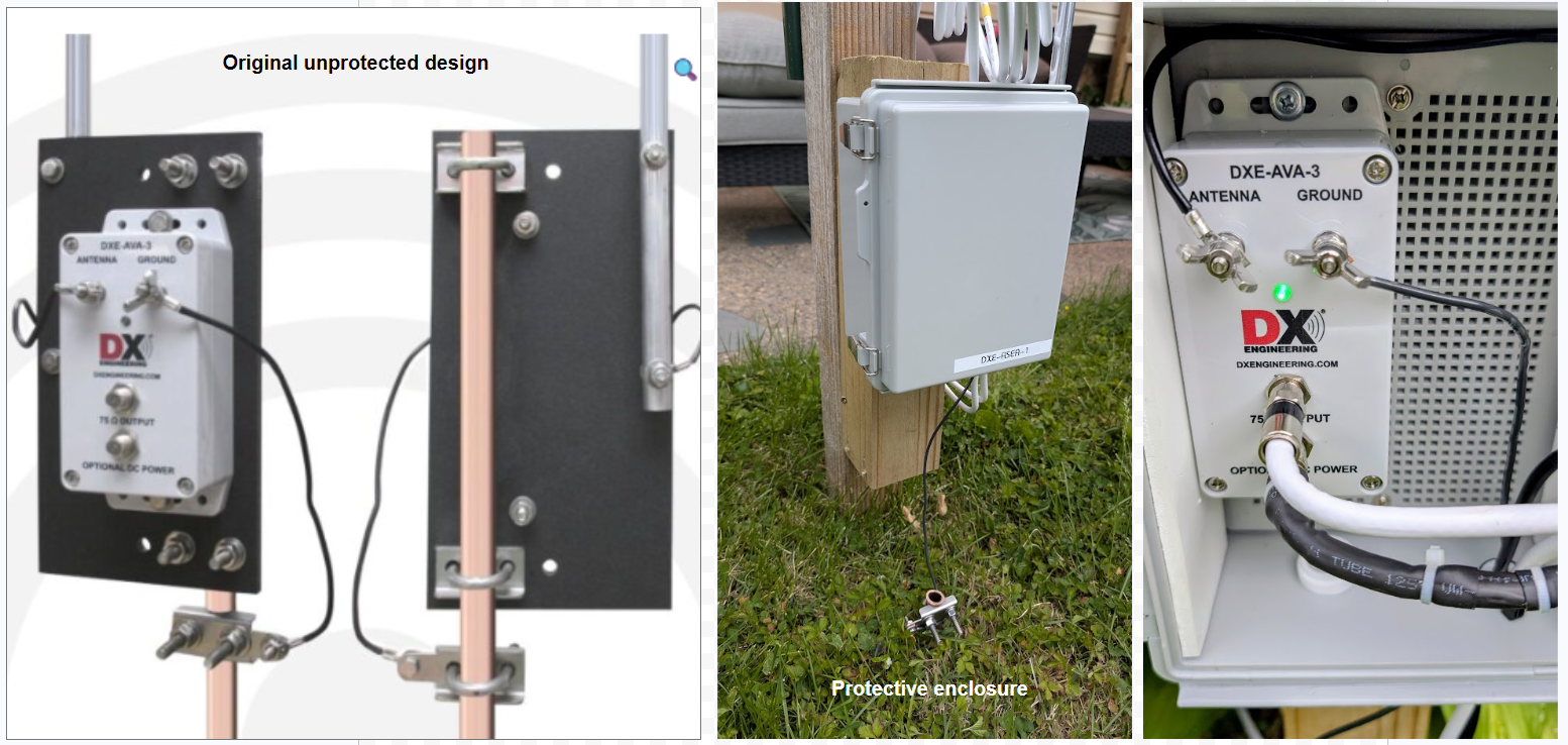
- Modifications to the outside mounting configuration The antenna’s physical design is lacking in sufficient protection from rain, snow or other environmental challenges. I have elected to incorporate the entire unit into a sealed ABS utility box, mounted on a 4X4 pressure-treated post. The ground rod is 1/2” common copper pipe driven into the soil to 4’. Since the Bias-T option is deselected via J2 and J3, 12VDC is provided to the lower F connector via a simple adapter to the DC source. Both the RG6 and the 12ga DC wiring are 50’ long and have nominal RF loss or voltage drop.
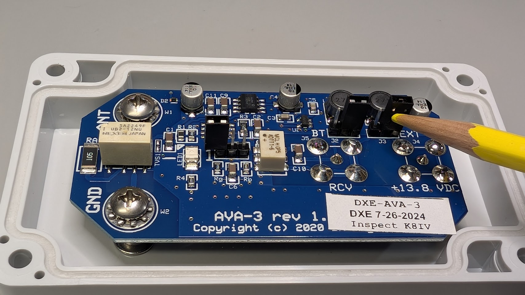
Configure the Leo Bodnar LBE-1420 GPS clock output
- Visit the Leo Bodnar website and select your GPS Disciplined Oscillator model and download the configuration software for your operating system. Note: Use a different PC than the PSWS Beelink to run the Bodnar configuration software.
- Connect the GPS to your PC — the LED will light up and start the configuration software
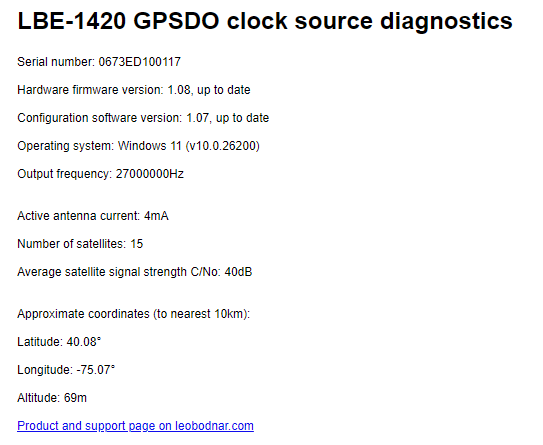
- In the
Hzbox, enter27000000and click Set Frequency > This sets the output to 27 MHz, which is the required clock frequency for the RX-888 - Disconnect the GPS from your PC
Confirm LBE-1420 GPSDO via the
Diagnosticsbutton
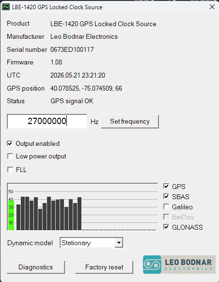
Connect the LBE-1420 GPS clock’s SMA output to the RX-888 TAPR clock-modified GPS-in on the new end board, then connect both the RX888 and the LBE-1420 devices to the PSWS Beelink computer via their USB cables to a USB-3 port (blue tab).
📷 Receiver Setup Schematic: The Beelink PC, RX-888 Receiver, and GPS Disciplined Oscillator are connected as follows:
- 🟡 Yellow — GPS Oscillator to RX-888
- 🔴 Red — GPS Oscillator to PC
- 🟢 Green — RX-888 to PC
This completes the required component modifications. Next, check the Software page to configure the Beelink PC with Linux 24.04.n and WSPRDaemon.